Stark3 (Revo 3) Communication Protocol
1. Introduction
1.1 Purpose
This document is designed to guide users in communicating with the Stark3 (Revo 3) dexterous hand using RS485 or CAN FD interfaces, enabling device configuration, motion control, status acquisition, and tactile data reading.
1.2 Supported Interfaces
- RS485
- CAN FD
2. Modbus RTU Protocol
RS485 communication on the Stark3 hand uses the standard Modbus RTU protocol format.
2.1 Frame Format
| Header / Device ID | Function Code | Data | CRC16 |
|---|---|---|---|
| 1 Byte | 1 Byte | N Bytes | 2 Bytes |
2.2 Field Descriptions
| Field | Description |
|---|---|
| Header/Device ID | Slave device address |
| Function Code | Modbus function code (e.g., 03H: Read Holding Registers; 04H: Read Input Registers; 06H: Write Single Holding Register; 10H: Write Multiple Holding Registers) |
| Data | Data payload, varying based on the function code and register address |
| CRC16 | CRC-16 (Modbus) checksum, low byte first, high byte last |
3. CAN FD Encapsulation Format
When using the CAN FD interface, the underlying communication still contains Modbus protocol data, which is encapsulated and transmitted within a 29-bit CAN FD extended frame.
3.1 CAN FD ID Format
The 29-bit CAN FD ID is allocated as follows:
| Bits | Field | Description |
|---|---|---|
| 28 ~ 24 | Reserved | Fixed to 0 |
| 23 ~ 16 | Device ID | Slave device address |
| 15 ~ 8 | Master ID | Host device ID (defined by host) |
| 7 ~ 0 | Payload Length | Actual length of active data payload (Bytes) |
Default Device ID
| Device | Default Device ID (Decimal) | Default Device ID (Hexadecimal) |
|---|---|---|
| Left Hand | 126 | 0x7E |
| Right Hand | 127 | 0x7F |
3.2 Frame Formats
Host Transmission Frame
| CAN FD ID (29-bit) | Data Segment (Payload, ≤ 64 Bytes) |
|---|---|
| Device ID + Master ID + Payload Length | Complete Modbus RTU request frame (including checksums) |
Device Reply Frame
| CAN FD ID (29-bit) | Data Segment (Payload, ≤ 64 Bytes) |
|---|---|
| Device ID + Master ID + Payload Length | Complete Modbus RTU response frame |
4. Register Map Overview
Stark3 registers are planned as follows:
| Address Range | Register Type | Category |
|---|---|---|
| 0 ~ 199 | Holding Register | System Configuration |
| 200 ~ 399 | Holding Register | Motor Parameters |
| 1000 ~ 1599 | Holding Register | Control Commands |
| 1800 ~ 1999 | Input Register | System Status |
| 2030 ~ 2999 | Input Register | Motor Feedback |
| 3000 ~ 3999 | Input Register | Device Information |
| 4000 ~ 5000 | Input Register | Tactile Data |
5. System Configuration Registers
System configuration registers (address range 0~199) support read/write access.
| Address | Name | Access | Description |
|---|---|---|---|
| 60 ~ 80 | Motor Zero Offset | RW | Unit: 0.01° (transmitted as value × 100). Total 21 joints. |
| 101 | Hand Identity | RO | 1 = Right hand, 2 = Left hand |
| 102 | Restore Finger Defaults | WO | Write specific value to restore default finger parameters. |
| 105 | Buzzer Switch | RW | 0 = Off, 1 = On |
| 106 | Vibration Motor Switch | RW | 0 = Off, 1 = On |
| 107 | Touch Screen Switch | RW | 0 = Off, 1 = On |
| 108 | Device ID | RW | Default: 126 for Left hand, 127 for Right hand |
| 109 | RS485 Baudrate | RW | See 5.1 RS485 Baudrate |
| 110 | CAN FD Baudrate | RW | See 5.2 CAN FD Baudrate |
| 112 | Auto Calibration | RW | 0 = Off, 1 = On (automatically run calibration on boot) |
| 118 | Teaching Mode | RW | Write 1 to enter, 0 to exit |
| 119 | Emergency Stop | RW | Write 1 to stop all motors, 0 to resume normal operation |
| 131 | Auto-clear Motor Error | RW | 0 = Off (default), 1 = On |
5.1 RS485 Baudrate
| Value | Baudrate |
|---|---|
| 0 | 1 Mbps |
| 1 | 2 Mbps |
| 2 | 3 Mbps |
| 3 | 5 Mbps |
5.2 CAN FD Baudrate
| Value | Baudrate |
|---|---|
| 0 | 1 Mbps |
| 1 | 2 Mbps |
| 2 | 4 Mbps |
| 3 | 5 Mbps |
6. Motor Parameters
The units for motor parameters are defined as follows:
- Position: Degrees (°)
- Velocity: Revolutions per minute (rpm)
- Current: Milliamperes (mA)
💡 Numerical Scaling Details
To maintain data precision, position and velocity values are transmitted as integers using actual value × 100.
- Angle Example: Target position
90.00°→ transmitted register value is9000. - Velocity Example: Target velocity
50.00 rpm→ transmitted register value is5000. - Current Example: Target protection currents directly use the physical value in mA.
6.1 Global Protection Current
| Address | Parameter | Access | Description |
|---|---|---|---|
| 200 | All Joints Protection Current (mA) | WO | Configures protection current for all 21 joints at once |
6.2 Single Joint Protection Current
| Address | Parameter | Access | Description |
|---|---|---|---|
| 201 ~ 221 | Joint Protection Current (mA) | RW | Maximum allowed current for joints 0 to 20 |
6.3 Joint Movement Limits
| Address | Parameter | Access | Description |
|---|---|---|---|
| 240 ~ 260 | Min Position Limit (° × 100) | RW | Physical minimum position limit for joints 0 to 20 |
| 270 ~ 290 | Max Position Limit (° × 100) | RW | Physical maximum position limit for joints 0 to 20 |
| 300 ~ 320 | Min Velocity Limit (rpm × 100) | RW | Minimum speed limit for joints 0 to 20 |
| 321 ~ 341 | Max Velocity Limit (rpm × 100) | RW | Maximum speed limit for joints 0 to 20 |
7. Control Commands
Stark3 support MIT impedance control mode.
7.1 MIT Control Formula
Data Scaling
- , , Position, Velocity are transmitted as actual value × 100.
- Current ( ) is transmitted directly in mA.
Example:
- target = 15.00 transmitted value = 1500
- target = 0.50 transmitted value = 50
- Position target = 90.00° transmitted value = 9000
- Velocity target = 50.00 rpm transmitted value = 5000
- Current ( ) target = 1000 mA transmitted value = 1000
7.2 Single Joint MIT Control
Enables standalone control of a specific joint:
| Address | Parameter | Description |
|---|---|---|
| 1050 | Joint ID | Target joint number (0 ~ 20) |
| 1051 | Proportional stiffness gain (value × 100) | |
| 1052 | Derivative damping gain (value × 100) | |
| 1053 | Position | Target position (° × 100) |
| 1054 | Velocity | Target velocity (rpm × 100) |
| 1055 | Current ( ) | Feedforward current (mA) |
7.3 Multi-Joint MIT Control
Provides a continuous register map block for bulk updates of multiple joints:
| Address Range | Target Joint | Parameter Array | Description |
|---|---|---|---|
| 1100 ~ 1104 | Joint 0 | 5 consecutive registers | |
| 1105 ~ 1109 | Joint 1 | 5 consecutive registers | |
| ... | ... | ... | ... |
| 1195 ~ 1199 | Joint 19 | 5 consecutive registers | |
| 1200 ~ 1204 | Joint 20 | 5 consecutive registers |
7.4 Bulk Parameter Controls
Enables targeted bulk updates for a single MIT parameter across all joints:
| Address Range | Parameter | Description |
|---|---|---|
| 1300 ~ 1320 | List | Proportional gain ( ) for all 21 joints |
| 1321 ~ 1341 | List | Damping gain ( ) for all 21 joints |
| 1342 ~ 1362 | Position List | Target position ( ) for all 21 joints |
| 1363 ~ 1383 | Velocity List | Target velocity ( ) for all 21 joints |
| 1384 ~ 1404 | List | Feedforward current ( ) for all 21 joints |
7.5 Four-Finger MIT Control
Used to control the index, middle, ring, or pinky finger:
| Address | Parameter | Description |
|---|---|---|
| 1520 | Finger Index | 1 = Index, 2 = Middle, 3 = Ring, 4 = Pinky |
| 1521 ~ 1540 | Parameter Array | Total 20 registers containing gains and references: 1. Abduction/Adduction MCP (5 registers) 2. Flexion/Extension MCP (5 registers) 3. PIP (5 registers) 4. DIP (5 registers) |
7.6 Thumb MIT Control
Used to control the 5-DOF thumb structure:
| Address Range | Parameter Array | Description |
|---|---|---|
| 1550 ~ 1574 | 5-DOF Parameters | Total 25 registers in sequence: 1. CMC Flexion/Extension (5 registers) 2. CMC Abduction/Adduction (5 registers) 3. MCP (5 registers) 4. IP (5 registers) 5. DIP (5 registers) |
8. System Status
System status registers (address range 1800~1999) are read-only input registers.
| Address | Parameter | Unit | Description |
|---|---|---|---|
| 1800 | System Status Code | — | See 8.1 System Status Code Definitions |
| 1801 | Total Current | mA | Current consumption of the hand |
| 1802 | Total Voltage | V | Supply voltage of the hand |
| 1803 | Total Power | W | Power consumption of the hand |
| 1804 | System Temperature | ℃ | Temperature of the main control board |
8.1 System Status Code Definitions
The status code register (1800) uses high and low bytes to indicate errors:
- High 8 Bits (High Byte): Core fault flag
0= Normal1= Fault
- Low 8 Bits (Low Byte): Detailed exception categories
0= Normal1= Communication failure2= Uncalibrated3= Temperature abnormal
9. Motor Feedback
Real-time state monitoring of the 21 joint motors via input registers (2030~2999).
| Address Range | Parameter | Unit | Description |
|---|---|---|---|
| 2030 ~ 2050 | Motor Velocity | rpm × 100 | Current rotational speed of motors 0 ~ 20 |
| 2060 ~ 2080 | Motor Position | ° × 100 | Current angular position of motors 0 ~ 20 |
| 2090 ~ 2110 | Motor Current | mA | Current drive current of motors 0 ~ 20 |
| 2120 ~ 2140 | Motor Status Code | Bit field | See 9.1 Motor Status Code Definitions |
| 2150 ~ 2170 | Motor Temperature | ℃ | Temperature of motors 0 ~ 20 (internal or driver IC) |
9.1 Motor Status Code Definitions
The motor status registers (2120~2140) use bitwise flags to report faults:
| Bit | Description |
|---|---|
| 0 | Over-current |
| 1 | Over-voltage |
| 2 | Under-voltage |
| 3 | Over-temperature |
| 4 | Current Spike |
| 5 | Calibration Failed |
| 8 | Motor Stall |
| 9 | Calibrating |
| 11 | Motor Running |
10. Device Information
Device information registers (address range 3000~3999) are read-only.
| Address Range | Parameter Name | Format / Details |
|---|---|---|
| 3030 ~ 3039 | Firmware Version | RO, Big-Endian ASCII string |
| 3040 ~ 3049 | Hardware Version | RO, Big-Endian ASCII string |
| 3050 ~ 3059 | Product SN | RO, Big-Endian ASCII string |
| 3060 ~ 3269 | Motor SN | RO, Big-Endian ASCII string, 10 registers per motor SN (21 motors total) |
| 3300 ~ 3320 | Motor Firmware Version | RO, binary version representation |
10.1 Encoding Details
Versions & Serial Numbers (ASCII)
Strings are stored in Big-Endian byte order inside the registers. Each uint16_t register holds 2 characters:
- High Byte: Holds the first character
- Low Byte: Holds the second character
Each field uses 10 registers, supporting a maximum string length of 20 characters (including trailing null \0).
Decoding Example:
| Register Array (Big-Endian uint16_t) | Hexadecimal Bytes | Decoded ASCII String |
|---|---|---|
0x534E, 0x3132, 0x3334, 0x3536, 0x3738, 0x3930, 0x3132, 0x3334, 0x3500 | 53 4E 31 32 33 34 35 36 37 38 39 30 31 32 33 34 35 00 | "SN123456789012345" |
Motor Firmware Version
The motor firmware version is stored in a single uint16_t split into:
- High Byte: Major version
- Low Byte: Minor version
Parsing Format: Version = V[Major].[Minor]
- E.g., read value
0x0105represents versionV1.5.
11. Resistive Tactile Module
Stark3 features a high-density tactile pressure array, split between palm and finger modules.
11.1 Tactile Module Specification
| Module Type | Active Points | Calibrated Resultant Forces |
|---|---|---|
| Palm | 36 | 1 |
| Thumb Tip | 31 | 3 |
| Thumb Pad | 57 | 6 |
| Four Finger Tips (each) | 21 | 3 |
| Four Finger Pads (each) | 52 | 5 |
11.2 Tactile Control Registers
| Address | Description |
|---|---|
| 4000 ~ 4010 | Tactile Module Enable (corresponds to module IDs 0 ~ 10) |
| 4011 | Zero-out Pressure (WO, applies to all modules) |
| 4012 ~ 4022 | Zero-out Specific Module (WO, corresponds to module IDs 0 ~ 10) |
| 4023 | Tactile Data Mode (0 = Raw array pressure, 1 = Calibrated pressure values) |
11.3 Calibrated Resultant Forces
💡 Resultant Force Definition
Resultant Force = Sum of all calibrated pressure values within the mapped sub-regions of the module.
Palm & Thumb
| Address | Description | Detail |
|---|---|---|
| 4100 | Palm Force | Entire palm area |
| 4101 ~ 4103 | Thumb Tip 1 ~ 3 | 3 sub-regions of the thumb tip |
| 4104 ~ 4109 | Thumb Pad 1 ~ 6 | 6 sub-regions of the thumb pad |
Index Finger
| Address | Description | Detail |
|---|---|---|
| 4110 ~ 4112 | Index Tip 1 ~ 3 | Index finger tip sub-regions |
| 4113 ~ 4117 | Index Pad 1 ~ 5 | Index finger pad sub-regions |
Middle Finger
| Address | Description | Detail |
|---|---|---|
| 4118 ~ 4120 | Middle Tip 1 ~ 3 | Middle finger tip sub-regions |
| 4121 ~ 4125 | Middle Pad 1 ~ 5 | Middle finger pad sub-regions |
Ring Finger
| Address | Description | Detail |
|---|---|---|
| 4126 ~ 4128 | Ring Tip 1 ~ 3 | Ring finger tip sub-regions |
| 4129 ~ 4133 | Ring Pad 1 ~ 5 | Ring finger pad sub-regions |
Pinky Finger
| Address | Description | Detail |
|---|---|---|
| 4134 ~ 4136 | Pinky Tip 1 ~ 3 | Pinky finger tip sub-regions |
| 4137 ~ 4141 | Pinky Pad 1 ~ 5 | Pinky finger pad sub-regions |
11.4 Tactile Array Data Registers
Real-time reading of raw or calibrated array values:
| Module Type | Address Range | Total Points |
|---|---|---|
| Palm | 4200 ~ 4235 | 36 points |
| Thumb Tip | 4250 ~ 4280 | 31 points |
| Thumb Pad | 4290 ~ 4346 | 57 points |
| Index Tip | 4350 ~ 4370 | 21 points |
| Index Pad | 4400 ~ 4451 | 52 points |
| Middle Tip | 4460 ~ 4480 | 21 points |
| Middle Pad | 4500 ~ 4551 | 52 points |
| Ring Tip | 4560 ~ 4580 | 21 points |
| Ring Pad | 4600 ~ 4651 | 52 points |
| Pinky Tip | 4660 ~ 4680 | 21 points |
| Pinky Pad | 4700 ~ 4751 | 52 points |
11.5 Tactile Module Index Definition
| Module ID | Module Name |
|---|---|
| 0 | Palm Tactile |
| 1 | Thumb Tip |
| 2 | Thumb Pad |
| 3 | Index Tip |
| 4 | Index Pad |
| 5 | Middle Tip |
| 6 | Middle Pad |
| 7 | Ring Tip |
| 8 | Ring Pad |
| 9 | Pinky Tip |
| 10 | Pinky Pad |
12. Joint ID Definitions
The Stark3 hand has 21 active joints. Refer to the diagram below for the ID mapping of each joint:
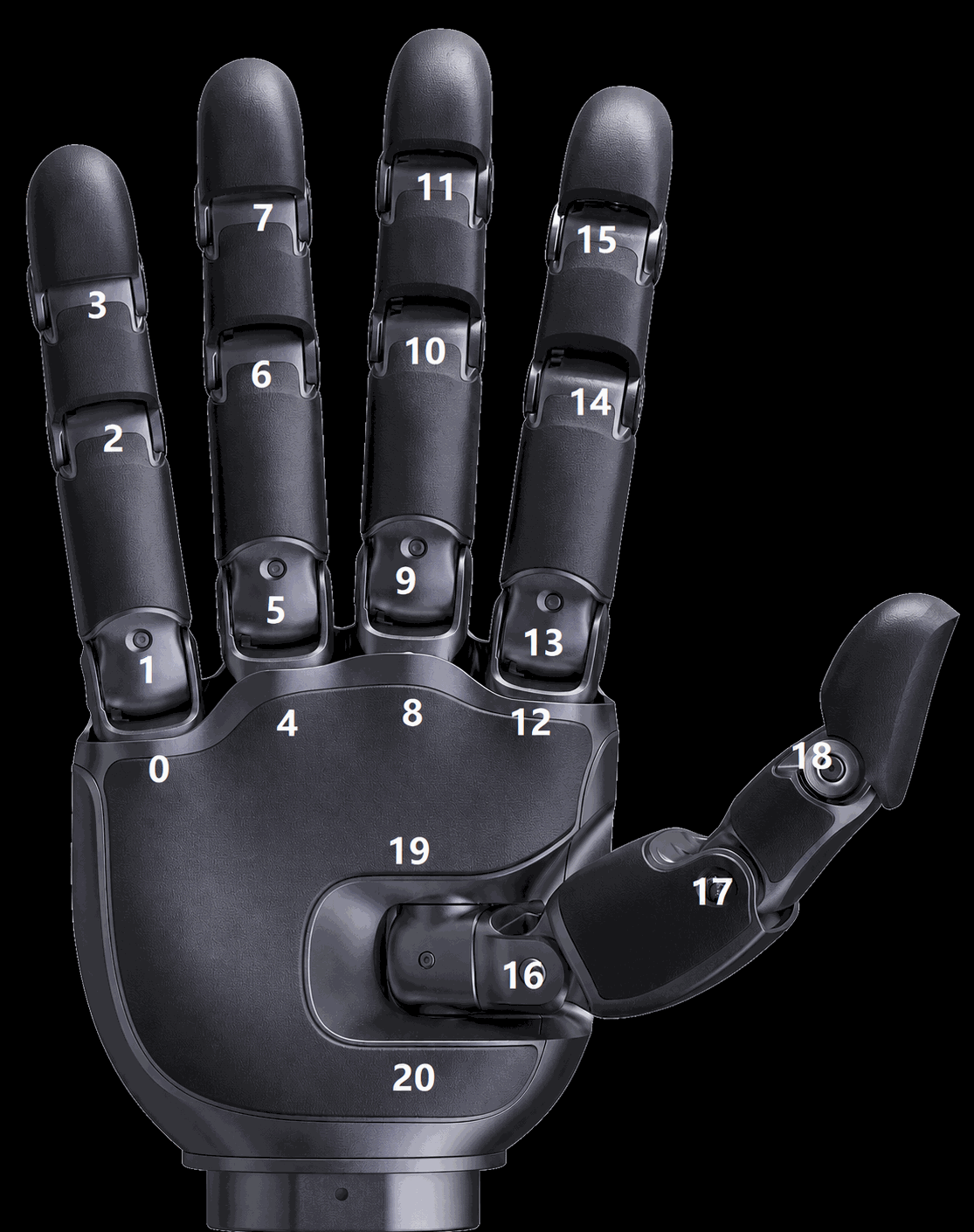 Stark3 (Revo 3) Dexterous Hand - Physical layout of 21 active joint motor IDs