Revo 2 dexterous hand Communication Protocol Design
Revo 2 Touch Edition dexterous hand supports 3 types of external communication interfaces.:RS485、CAN FD、EtherCAT(Click here to learn about the EC protocol description.)Design a protocol compatible with both 485 and CAN FD communication interfaces, ensuring high efficiency, reliability, and scalability of communication based on compatibility with different communication protocols.
Communication Interface Features
RS485 Features
- Communication speed:Up to 10 Mbps, commonly used rate is 9600 bps~1 Mbps。
- Frame length: Supports variable-length frames, with the maximum frame length constrained by the specific application.
- Verification method:The software needs to implement CRC16 or checksum verification methods to adapt to complex electromagnetic environments.
- Communication mode:Half-duplex communication requires a collision detection mechanism.
- Reliability:Strong anti-interference ability, suitable for long-distance communication.
CAN FD Features
- Communication speed:The data segment rate can reach 5 Mbps, while the header maintains the traditional CAN speed.
- Frame length:Supports up to 64-byte data segments, extending CAN's data payload capability.
- Verification method:Hardware built-in verification, no software implementation required.
- Communication mode:Compatible with traditional CAN communication devices.
Compatibility Protocol Design
Modbus-RTU Protocol is a master-slave request-response communication protocol, widely used in industrial automation systems. The protocol frame includes an address, function code, data field, and CRC check to ensure the reliability of communication.
Data frame format:
| Header/Device ID | Function Code | Data | CRC16 |
|---|---|---|---|
| 1byte | 1byte | n bytes | 2 Bytes |
Header/Device ID: Device identifier, used to distinguish between different devices. Function Code: Function code, indicating the type of operation requested. Data: Data field, containing the data for the specific operation. CRC16: CRC check, used to verify the integrity of the data.
RS485Compatible Modbus RTU:
RS485 does not define a specific communication protocol itself, but is usually used in conjunction with the Modbus RTU protocol and is widely used for data transmission in industrial automation and monitoring systems.
CANFD Compatible Modbus RTU:
Canfd uses extended frames, and the arbitration frame baud rate is fixed at 1 MbThe data field in the CAN FD protocol can include the Device ID, master ID, and data length in the frame ID, and the data field contains the entire Modbus RTU format.
Host sends frame:
| CAN FD ID(29bit) | Data (≤64Bytes) | |||
|---|---|---|---|---|
| 24~28bit 0b00000 16~23bit Device ID 8~15bit Master ID 0 ~7bit Payload len | Header/Device ID | Function Code | Data | CRC16 |
Device response frame
| CAN FD ID(29bit) | Data (≤64Bytes) | |||
|---|---|---|---|---|
| 24~28bit 0b00000 16~23bit Device ID 8~15bit Master ID 0 ~7bit Payload len | Header/Device ID | Function Code | Data | CRC16 |
Function code
The function code is used to identify the type of operation requested. Each function code corresponds to a specific operation and is mainly used to read data from the device, write data, or perform other control tasks.
| Function Code | Description |
|---|---|
| 03H | Read Holding Registers |
| 06H | Write Single Holding Register |
| 10H | Write Multiple Holding Registers |
| 04H | Read Input Registers |
Registers
Hand Registers (Control Type)
| Address | Type | Description | Length | Properties |
|---|---|---|---|---|
| 900 | Holding Register | Entry OTA | 2 bytes | W |
| 901 | Holding Register | Left/Right Hand Read | 2 bytes | R |
| 902 | Holding Register | Internal Gesture Restore Default | 2 bytes | W |
| 903 | Holding Register | Restore Factory Settings | 2 bytes | W |
| 904 | Holding Register | Backhand Light Switch | 2 bytes | W/R |
| 905 | Holding Register | Buzzer Switch | 2 bytes | W/R |
| 906 | Holding Register | Vibration Motor Switch | 2 bytes | W/R |
| 910 | Holding Register | Factory KEY | 20Bytes(10 uint16) | W/R |
| 920 | Holding Register | SN | 20Bytes(10 uint16) | W/R |
| 930 | Holding Register | Thumb Flex Protection Current | 2 bytes | W/R |
| 931 | Holding Register | Thumb Aux Protection Current | 2 bytes | W/R |
| 932 | Holding Register | Index Finger Protection Current | 2 bytes | W/R |
| 933 | Holding Register | Middle Finger Protection Current | 2 bytes | W/R |
| 934 | Holding Register | Ring Finger Protection Current | 2 bytes | W/R |
| 935 | Holding Register | Little Finger Protection Current | 2 bytes | W/R |
| 936 | Holding Register | Thumb Aux Lock Current | 2 bytes | W/R |
| 937 | Holding Register | Unit Mode Setting | 2 bytes | W/R |
| 938 | Holding Register | Finger Minimum Position Setting | 4 bytes | W |
| 940 | Holding Register | Finger Maximum Position Setting | 4 bytes | W |
| 942 | Holding Register | Finger Maximum Speed Setting | 4 bytes | W |
| 944 | Holding Register | Finger Maximum Current Setting | 4 bytes | W |
| 946 | Holding Register | Finger Minimum Position Reading | 12 bytes | R |
| 952 | Holding Register | Finger Maximum Position Reading | 12 bytes | R |
| 958 | Holding Register | Finger Maximum Speed Reading | 12 bytes | R |
| 964 | Holding Register | Finger Maximum Current Reading | 12 bytes | R |
| 970 | Holding Register | Tactile Manufacturer | 2 bytes | R |
| 1000 | Holding Register | Device ID | 2 bytes | W/R |
| 1001 | Holding Register | RS485 Baud Rate | 2 bytes | W/R |
| 1002 | Holding Register | CANFD Baud Rate | 2 bytes | W/R |
| 1003 | Holding Register | CANFD arbitration field sample point configuration | 2bytes | W/R |
| 1009 | Holding Register | Store Data/Restart | 2 bytes | W/R |
| 1010 | Holding Register | Multi-Finger Position Time Control | 24 bytes (12 uint16) | W/R |
| 1022 | Holding Register | Multi-Finger Position Speed Control | 24 bytes (12 uint16) | W/R |
| 1034 | Holding Register | Multi-Finger Speed Control | 12 bytes (6 uint16) | W/R |
| 1040 | Holding Register | Multi-Finger Current Control | 12 bytes (6 uint16) | W/R |
| 1046 | Holding Register | Multi-Finger PWM Control | 12 bytes (6 uint16) | W/R |
| 1052 | Holding Register | Single Finger Position Time Control | 6 bytes (3 uint16) | W |
| 1055 | Holding Register | Single Finger Position Speed Control | 6 bytes (3 uint16) | W |
| 1058 | Holding Register | Single Finger Speed Control | 4 Bytes (2 uint16) | W |
| 1060 | Holding Register | Single Finger Current Control | 4 Bytes (2 uint16) | W |
| 1062 | Holding Register | Single Finger PWM Control | 4 Bytes (2 uint16) | W |
| 1064 | Holding Register | LED Settings | 2 bytes | W/R |
| 1065 | Holding Register | Turbo Mode | 2 bytes | W/R |
| 1066 | Holding Register | Turbo Mode Time Parameters | 4 bytes | W/R |
| 1068 | Holding Register | Position Auto-Calibration | 2 bytes | W/R |
| 1069 | Holding Register | Position Calibration | 2 bytes | W |
| 1070 | Holding Register | Fast Position Control Mode | 6 bytes (3 uint16) | W |
| 1098 | Holding Register | ACTION_CMD_ID | 2bytes(1 uint16) | W |
| 1099 | Holding Register | ACTION_STEP_NUMBER | 2bytes(1 uint16) | W/R |
| 1100 | Holding Register | ACTION_STEP_PARAMS | 54bytes(27 uint16) | W/R |
| 2000 | Input Register | Actual Position Value | 12 bytes (6 uint16) | R |
| 2006 | Input Register | Actual Speed Value | 12 bytes (6 uint16) | R |
| 2012 | Input Register | Actual Current Value | 12 bytes (6 uint16) | R |
| 2018 | Input Register | Motor Status | 12 bytes (6 uint16) | R |
| 2025 | Input Register | Button Status | 2 bytes | R |
| 3000 | Input Register | FW Version | 20 bytes (10 uint16) | R |
| 3010 | Input Register | SN | 20 bytes (10 uint16) | R |
Tactile Module Register
Capacitive
| Address | Type | Description | Length | Property |
|---|---|---|---|---|
| 4000 | Holding Register | Thumb Tactile Switch | 2Byte | W/R |
| 4001 | Holding Register | Index Finger Tactile Switch | 2Byte | W/R |
| 4002 | Holding Register | Middle Finger Tactile Switch | 2Byte | W/R |
| 4003 | Holding Register | Ring Finger Tactile Switch | 2Byte | W/R |
| 4004 | Holding Register | Little Finger Tactile Switch | 2Byte | W/R |
| 4005 | Holding Register | Thumb Haptic Reset | 2 bytes | w |
| 4006 | Holding Register | Index Finger Haptic Reset | 2 bytes | w |
| 4007 | Holding Register | Middle Finger Haptic Reset | 2 bytes | w |
| 4008 | Holding Register | Ring Finger Haptic Reset | 2 bytes | w |
| 4009 | Holding Register | Little Finger Haptic Reset | 2 bytes | w |
| 4010 | Holding Register | Thumb Haptic Parameter Calibration | 2 bytes | w |
| 4011 | Holding Register | Index Finger Haptic Parameter Calibration | 2 bytes | w |
| 4012 | Holding Register | Middle Finger Haptic Parameter Calibration | 2 bytes | w |
| 4013 | Holding Register | Ring Finger Haptic Parameter Calibration | 2 bytes | w |
| 4014 | Holding Register | Little Finger Haptic Parameter Calibration | 2 bytes | w |
| 4100 | Input Register | Thumb Tactile Version | 20 Bytes (10 uint16) | R |
| 4110 | Input Register | Index Finger Tactile Version | 20 Bytes (10 uint16) | R |
| 4120 | Input Register | Middle Finger Tactile Version | 20 Bytes (10 uint16) | R |
| 4130 | Input Register | Ring Finger Tactile Version | 20 Bytes (10 uint16) | R |
| 4140 | Input Register | Little Finger Tactile Version | 20 Bytes (10 uint16) | R |
| 4200 | Input Register | Multi-finger 3D Force | 30 Bytes (15 uint16) | R |
| 4215 | Input Register | Multi-finger Proximity Value | 20 Bytes (10 uint16) | R |
| 4225 | Input Register | Multi-finger Tactile Status | 10 Bytes (5 uint16) | R |
| 4250 | Input Register | Thumb 3D Force, Proximity Value, Tactile Status | 12 Bytes (6 uint16) | R |
| 4256 | Input Register | Index Finger 3D Force, Proximity Value, Tactile Status | 12 Bytes (6 uint16) | R |
| 4262 | Input Register | Middle Finger 3D Force, Proximity Value, Tactile Status | 12 Bytes (6 uint16) | R |
| 4268 | Input Register | Ring Finger 3D Force, Proximity Value, Tactile Status | 12 Bytes (6 uint16) | R |
| 4274 | Input Register | Little Finger 3D Force, Proximity Value, Tactile Status | 12 Bytes (6 uint16) | R |
| 4300 | Input Register | Thumb Tactile Raw Data | 24 bytes (12 uint16) | R |
| 4312 | Input Register | Index Finger Tactile Raw Data | 24 bytes (12 uint16) | R |
| 4324 | Input Register | Middle Finger Tactile Raw Data | 24 bytes (12 uint16) | R |
| 4336 | Input Register | Ring Finger Tactile Raw Data | 24 bytes (12 uint16) | R |
| 4348 | Input Register | Little Finger Tactile Raw Data | 24 bytes (12 uint16) | R |
Pressure Sensing
| Starting Address | Register Type | Name | Data Length | Description | Attributes |
|---|---|---|---|---|---|
| 6000 | Holding Register | Tactile Data Type | 2 Bytes | 0: Raw Value 1: Calibrated Value | W/R |
| 6005 | Input Register | Five-Finger Combined Force | 10 Bytes | 5 fingers, 2 bytes per point | R |
| 6010 | Input Register | Thumb Tactile Data | 18 Bytes | 9 points, 2 bytes per point | R |
| 6019 | Input Register | Index Finger Tactile Data | 18 Bytes | 9 points, 2 bytes per point | R |
| 6028 | Input Register | Middle Finger Tactile Data | 18 Bytes | 9 points, 2 bytes per point | R |
| 6037 | Input Register | Ring Finger Tactile Data | 18 Bytes | 9 points, 2 bytes per point | R |
| 6046 | Input Register | Little Finger Tactile Data | 18 Bytes | 9 points, 2 bytes per point | R |
| 6070 | Input Register | Thumb Haptic Firmware Version | 10 Bytes | Firmware version string (vx.x.x) | R |
| 6080 | Input Register | Index Finger Haptic Firmware Version | 10 Bytes | Firmware version string (vx.x.x) | R |
| 6090 | Input Register | Middle Finger Haptic Firmware Version | 10 Bytes | Firmware version string (vx.x.x) | R |
| 6100 | Input Register | Ring Finger Haptic Firmware Version | 10 Bytes | Firmware version string (vx.x.x) | R |
| 6110 | Input Register | Little Finger Haptic Firmware Version | 10 Bytes | Firmware version string (vx.x.x) | R |
| 6130 | Holding Register | Thumb Haptic Switch | 2 Bytes | 0: Off; 1: On | W/R |
| 6131 | Holding Register | Index Finger Haptic Switch | 2 Bytes | 0: Off; 1: On | W/R |
| 6132 | Holding Register | Middle Finger Haptic Switch | 2 Bytes | 0: Off; 1: On | W/R |
| 6133 | Holding Register | Ring Finger Haptic Switch | 2 Bytes | 0: Off; 1: On | W/R |
| 6134 | Holding Register | Little Finger Haptic Switch | 2 Bytes | 0: Off; 1: On | W/R |
Register Description
Enter OTA/900
The settings take effect immediately after entering OTA.After entering OTA mode, pass throughUpgrade Agreement perform transmission mirroring.After the transmission is completed, the device enters bootloader mode to copy the firmware. Once the copy is finished, it automatically restarts and enters the normal program.
| Parameter Setting | Meaning |
|---|---|
| 1 | Enter OTA mode |
Left and Right Hand Reading / 901
To distinguish left and right hands, a register is used to read the current device's hand information.
| Register Address | Purpose | Value |
|---|---|---|
| 901 | Hand Recognition | 1: Right Hand 2: Left Hand |
Restore Default Values for Internal Gesture Sequence /902
| Register Address | Purpose | Type | Write Value | Function Description |
|---|---|---|---|---|
| 902 | Restore default values for 6 internal gestures | W | 0x5A5A | Restore default values for 6 internal gestures |
- Writing the fixed value
0x5A5Ato register902can trigger the device to restore all internal gesture sequences to factory default values. - Changes take effect and are saved immediately after restoring default gestures, and the default gesture configuration remains even after the device is restarted.
Factory Reset Register /903
| Register Address | Purpose | Type | Write Value | Function Description |
|---|---|---|---|---|
903 | Factory Reset | W | 0xA5A5 | Performs factory reset |
- Writing the fixed value
0xA5A5to register903can trigger the device to restore factory settings. - Default ID:Left hand → Reset to
0x7E(126);Right hand → Reset to0x7F(127) - RS485 Baud rate: Reset to
460800 bps. - CAN FD Baud rate: Reset to
5 Mbps.
Backlight Switch /904, Buzzer Switch /905, Vibration Motor Switch /906
| Register Address | Name | Description | Value Range | Default |
|---|---|---|---|---|
| 904 | Backlight Switch | Controls the back LED light on the hand | 0: Off1: On | 1 |
| 905 | Buzzer Switch | Controls whether the buzzer sounds | 0: Off1: On | 1 |
| 906 | Vibration Motor Switch | Controls whether the vibration motor is enabled (vibration) | 0: Off1: On | 0 |
Finger Protection Current Settings / 930-935
| Register Address | Purpose | Corresponding Finger | Unit | Range | Default Value (mA) |
|---|---|---|---|---|---|
| 930 | Thumb FLEX Protection Current | Thumb Tip (FLEX) | mA | 100 ~ 1500 | 500 |
| 931 | Thumb AUX Protection Current | Thumb Base (AUX) | mA | 100 ~ 1500 | 500 |
| 932 | Index Finger Protection Current | Index Finger | mA | 100 ~ 1500 | 500 |
| 933 | Middle Finger Protection Current | Middle Finger | mA | 100 ~ 1500 | 500 |
| 934 | Ring Finger Protection Current | Ring Finger | mA | 100 ~ 1500 | 500 |
| 935 | Little Finger Protection Current | Little Finger | mA | 100 ~ 1500 | 500 |
- This register can perform read and write operations, and is used to read and set the current protection threshold for the fingers.
- When writing the protection current, writing will be rejected if it exceeds the range.
- The written protection current is only effective during the current operation; it will automatically revert to the default value upon shutdown or restart.
Thumb AUX lock current /936
| Register Address | Purpose | Type | Unit | Range | Default Value |
|---|---|---|---|---|---|
| 936 | Thumb AUX Lock Current Setting | W/R | mA | 100-500 | 200 |
- The thumb AUX has no mechanical locking. Due to the rebound force of the wrinkled silicone, it is necessary to maintain the locking state using motor current.
Unit Mode Settings /937
Determine the units of input/output data for all fingers:
| Value | Mode Name | Input/Output Format |
|---|---|---|
| 0 | Normalized Mode | 0-1000 (no unit) |
| 1 | Physical Unit Mode | Angle (°), Speed (°/s), Current (mA) |
- Mode Description:
| Mode | Position Range | Speed Range | Current Input Range | Description |
|---|---|---|---|---|
| Normalized Mode | 0-1000 (mapped to min-max position) | 0-1000 (mapped to max speed) | 0-1000 (mapped to max current) | Applicable for unitless control, where the master station does not need to care about specific hardware parameters |
| Physical Units Mode | Angle (°) | Angular Speed (°/s) | Current (mA) | Applicable for precise control, where physical values can be set directly |
Finger maximum/minimum value settings /938-944
All settings for maximum/minimum positions, maximum speed, and maximum current need carry Motor number + Target value,Each setting occupies 2 bytes of registers.
| ** Starting address of the register ** | Parameter type | Data format |
|---|---|---|
| 938 | Finger Minimum Position (°) | [Motor number] [Minimum position value] |
| 940 | Finger Maximum Position (°) | [Motor number] [Maximum position value] |
| 942 | Finger Maximum Speed (°/s) | [Motor number] [Maximum speed value] |
| 944 | Finger Maximum Current (mA) | [Motor number] [Maximum current value] |
- Default values for each finger:
| Finger Name | Motor Number | Default Minimum Position (°) | Default Maximum Position (°) | Default Maximum Speed (°/s) | Default Maximum Current (mA) |
|---|---|---|---|---|---|
| Thumb Flex | 0 | 0° | 59° | 145°/s | 1000mA |
| Thumb Aux | 1 | 0° | 90° | 150°/s | 1000mA |
| Index | 2 | 0° | 81° | 130°/s | 1000mA |
| Middle | 3 | 0° | 81° | 130°/s | 1000mA |
| Ring | 4 | 0° | 81° | 130°/s | 1000mA |
| Pinky | 5 | 0° | 81° | 130°/s | 1000mA |
Description:
- Position angle The minimum and maximum values can be modified.,The default minimum value is 0°, but it can be adjusted dynamically.
- The minimum values of speed and current are fixed at 0, non-configurable, while the maximum values can be dynamically adjusted.
- After shutting down, all fingers’s Maximum/minimum position, maximum speed, and maximum current will all restore to default values.
Finger Max/Min Value Readings /946-964
| Register Address | Purpose | Thumb Tip | Thumb Base | Index Finger | Middle Finger | Ring Finger | Little Finger |
|---|---|---|---|---|---|---|---|
| 946 - 951 | Minimum Position Readings (°) | 946 | 947 | 948 | 949 | 950 | 951 |
| 952 - 957 | Maximum Position Readings (°) | 952 | 953 | 954 | 955 | 956 | 957 |
| 958 - 963 | Maximum Speed Readings (°/s) | 958 | 959 | 960 | 961 | 962 | 963 |
| 964 - 969 | Maximum Current Readings (mA) | 964 | 965 | 966 | 967 | 968 | 969 |
Description
- Minimum/Maximum Position (°): Used to read the range of motion for each finger, where the minimum and maximum angles for each finger can be dynamically adjusted, but take effect only after powering on; they revert to default values after powering off.
- Maximum Speed (°/s): Used to read the maximum speed of finger movement, which is configurable, but takes effect only after powering on; it reverts to default values after powering off.
- Maximum Current (mA): Used to read the maximum allowable current for the finger drive motor, which is configurable, but takes effect only after powering on; it reverts to default values after powering off.
Haptic Vendor Type / 970
| Address | Name | Read/Write Type | Description |
|---|---|---|---|
| 970 | Haptic Vendor Type | R | 0: No haptics; 1: Capacitive; 2: Piezoresistive |
Modify Device ID / 1000
Modify Device ID. The set range is: 1 - 254.After setting the ID, it takes effect immediately and is saved to flash.
Default ID: Left hand default ID is 0x7e, right hand default ID is 0x7f.
RS485 Device Baud Rate/1001
RS485 device baud rate, you can set the parameters below:
| Setting Parameters | Baud Rate |
|---|---|
| 0 | 115200 |
| 1 | 57600 |
| 2 | 19200 |
| 3 | 460800 |
| 4 | 1000000 |
| 5 | 2000000 |
| 6 | 5000000 |
CANFD Device Baud Rate/1002
The baud rate of the CANFD device can be set with the parameters below
| Set Parameter | Baud Rate |
|---|---|
| 0 | 100 kbps |
| 1 | 125 kbps |
| 2 | 200 kbps |
| 3 | 250kbps |
| 4 | 400kbps |
| 5 | 500kbps |
| 6 | 800kbps |
| 7 | 1Mbps |
| 8 | 2Mbps |
| 9 | 4Mbps |
| 10 | 5Mbps |
CANFD Arbitration Field Sampling Point Configuration /1003
CANFD Arbitration domain sampling points can be set with the following parameters
| Set parameters | Baud rate / Sampling point |
|---|---|
| 0 | 1000 kbps 75% Sampling point |
| 1 | 1000 kbps 80% Sampling point |
** Restart/1009**
Set the Restart/1009 register, and the dexterous hand will restart.
Multiple Finger Position Time Control/1010
Each mechanical hand includes 6 motors, with the thumb driven by 2 motors. The table below lists the correspondence between registers and the motors for each finger.The value of the position register can be in a normalized range of 0 to 1000, or in an actual position range (unit: °).
To achieve a control precision of 0.1°, position values are uniformly scaled by a factor of 10 before being sent (i.e., 1 represents 0.1°). Here, 0 represents fully open, and 1000 represents fully closed.
The expected time register has a value range of 1 to 2000, with units in milliseconds (ms). When the set expected time is less than the fastest execution time allowed by the motor, the motor will operate at maximum speed.
| Finger | Register Address | Register Value |
|---|---|---|
| Thumb Flex | Position Register 1010 | 0 - 1000 or Minimum - Maximum Position (°) |
| Expected Time Register 1011 | 1-2000 | |
| Thumb Aux | Position Register 1012 | 0 - 1000 or Minimum - Maximum Position (°) |
| Expected Time Register 1013 | 1-2000 | |
| Index Finger | Position Register 1014 | 0 - 1000 or Minimum - Maximum Position (°) |
| Expected Time Register 1015 | 1-2000 | |
| Middle Finger | Position Register 1016 | 0 - 1000 or Minimum - Maximum Position (°) |
| Expected Time Register 1017 | 1-2000 | |
| Ring Finger | Position Register 1018 | 0 - 1000 or Minimum - Maximum Position (°) |
| Expected Time Register 1019 | 1-2000 | |
| Little Finger | Position Register 1020 | 0 - 1000 or Minimum - Maximum Position (°) |
| Expected Time Register 1021 | 1-2000 |
Multiple Finger Position Speed Control / 1022
Each robotic hand consists of 6 motors, with the thumb driven by 2 motors. The table below lists the correspondence between registers and the motors of each finger.The values of the position register can be either in the normalized range of 0 to 1000 or in actual angle range (unit: °).
To achieve a control precision of 0.1°, the position values are uniformly scaled up by a factor of 10 when issued (i.e., 1 represents 0.1°). Here, 0 represents fully open, while 1000 represents fully closed.
The expected speed register can be in a normalized range of 1 to 1000 or in the actual angular speed range (unit: °/s), which is used to control the rotation speed of the fingers.When the set expected speed exceeds the maximum speed of the motor, the motor will operate at its maximum speed.
| Finger | Register Address | Register Value |
|---|---|---|
| Thumb Flex | Position Register 1022 | 0 - 1000 or Minimum-Maximum Position (°) |
| Desired Speed Register 1023 | 1 - 1000 or Desired Speed (1-Maximum Speed °/s) | |
| Thumb Aux | Position Register 1024 | 0 - 1000 or Minimum-Maximum Position (°) |
| Desired Speed Register 1025 | 1 - 1000 or Desired Speed (1-Maximum Speed °/s) | |
| Index Finger | Position Register 1026 | 0 - 1000 or Minimum-Maximum Position (°) |
| Desired Speed Register 1027 | 1 - 1000 or Desired Speed (1-Maximum Speed °/s) | |
| Middle Finger | Position Register 1028 | 0 - 1000 or Minimum-Maximum Position (°) |
| Desired Speed Register 1029 | 1 - 1000 or Desired Speed (1-Maximum Speed °/s) | |
| Ring Finger | Position Register 1030 | 0 - 1000 or Minimum-Maximum Position (°) |
| Desired Speed Register 1031 | 1 - 1000 or Desired Speed (1-Maximum Speed °/s) | |
| Little Finger | Position Register 1032 | 0 - 1000 or Minimum-Maximum Position (°) |
| Desired Speed Register 1033 | 1 - 1000 or Desired Speed (1-Maximum Speed °/s) |
Multiple Finger Speed Control/1034
The normalization mode is set to a range of -1000 to 1000, and the physical unit mode range is (-maximum speed - miximum speed), where the sign indicates the direction: positive indicates the gripping direction, and negative indicates the releasing direction. The unit of speed value in physical unit mode is: °/s
| Register Address | Finger | Register Value |
|---|---|---|
| 1034 | Thumb Flex | -1000 - 1000 or Desired Speed (-maximum speed - miximum speed °/s) |
| 1035 | Thumb Aux | -1000 - 1000 or Desired Speed (-maximum speed - miximum speed °/s) |
| 1036 | Index Finger | -1000 - 1000 or Desired Speed (-maximum speed - miximum speed °/s) |
| 1037 | Middle Finger | -1000 - 1000 or Desired Speed (-maximum speed - miximum speed °/s) |
| 1038 | Ring Finger | -1000 - 1000 or Desired Speed (-maximum speed - miximum speed °/s) |
| 1039 | Little Finger | -1000 - 1000 or Desired Speed (-maximum speed - miximum speed °/s) |
Multi-finger Current Control / 1040
The normalization mode setting range is -1000 to 1000, and the physical unit mode range is (-maximum current - maximum current), where the sign indicates direction: positive for gripping direction and negative for releasing direction. The unit of the current value in physical unit mode is: mA
| Register Address | Finger | Register Value |
|---|---|---|
| 1040 | Thumb Flex | -1000 to 1000 or expected current (-maximum current - maximum current) |
| 1041 | Thumb Aux | -1000 to 1000 or expected current (-maximum current - maximum current) |
| 1042 | Index Finger | -1000 to 1000 or expected current (-maximum current - maximum current) |
| 1043 | Middle Finger | -1000 to 1000 or expected current (-maximum current - maximum current) |
| 1044 | Ring Finger | -1000 to 1000 or expected current (-maximum current - maximum current) |
| 1045 | Little Finger | -1000 to 1000 or expected current (-maximum current - maximum current) |
Multi-finger PWM Control / 1046
Finger PWM control, where the symbol indicates direction: positive indicates the gripping direction, and negative indicates the releasing direction.
| Register Address | Finger | Register Value |
|---|---|---|
| 1046 | Thumb Flex | -1000 - 1000 |
| 1047 | Thumb Aux | -1000 - 1000 |
| 1048 | Index Finger | -1000 - 1000 |
| 1049 | Middle Finger | -1000 - 1000 |
| 1050 | Ring Finger | -1000 - 1000 |
| 1051 | Little Finger | -1000 - 1000 |
Single Finger Position Time Control / 1052
In order to achieve a control precision of 0.1°, the position values are uniformly amplified by 10 times before being issued (i.e., 1 represents 0.1°).
| Register Address | Register Name | Register Value |
|---|---|---|
| 1052 | Finger number | 0-5 |
| 1053 | position | 1-1000 or Minimum - Maximum Position(°) |
| 1054 | Expected time | 1- 2000 |
Single Finger Position Speed Control / 1055
In order to achieve a control precision of 0.1°, the position values are uniformly amplified by 10 times before being sent out in physical quantity mode (i.e., 1 represents 0.1°).
| Register Address | Register Name | Register Value |
|---|---|---|
| 1055 | Finger number | 0-5 |
| 1056 | Position | 0-1000 or minimum-Maximum position(°) |
| 1057 | Expected speed(°/s) | 1 - 1000 or Expected speed(1-Maximum speed°/s) |
Single Finger Speed Control/1058
| Register Address | Register Name | Register Value |
|---|---|---|
| 1058 | Finger number | 0-5 |
| 1059 | Speed | -1000 - 1000 or Expected speed(-Maximum speed —— Miximum speed°/s) |
Single finger current control / 1060
| Register Address | Register Name | Register Value |
|---|---|---|
| 1060 | Finger number | 0-5 |
| 1061 | Current | -1000 - 1000或 Expected current (-maximum current —— maximum current mA) |
Single finger PWM control/1062
| Register Address | Register Name | Register Value |
|---|---|---|
| 1062 | Finger number | 0-5 |
| 1063 | PWM | -1000-1000 |
LED Control/1064
Register value
uint8_t led_mode = 1;
uint8_t led_color = 2;
uint16_t register_value = ((uint16_t)led_mode << 8) + led_color;| LED MODE | Description | Register Value |
|---|---|---|
| 1 | LED_MODE_SHUTDOWN | 1 |
| 2 | LED_MODE_KEEP | 2 |
| 3 | LED_MODE_BLINK | 3 |
| 4 | LED_MODE_ONE_SHOT | 4 |
| 5 | LED_MODE_BLINK0_5HZ | 5 |
| 6 | LED_MODE_BLINK2HZ | 6 |
| LED COLOR | Description | Register Value |
|---|---|---|
| 1 | LED_COLOR_R | 1 |
| 2 | LED_COLOR_G | 2 |
| 3 | LED_COLOR_RG | 3 |
| 4 | LED_COLOR_B | 4 |
| 5 | LED_COLOR_RB | 5 |
| 6 | LED_COLOR_GB | 6 |
| 7 | LED_COLOR_RGB | 7 |
Turbo Mode/1065
Turbo mode resets to the default off state after power loss.
| Register Value | Description |
|---|---|
| 0 | Off |
| 1 | On |
Turbo mode time parameters / 1066
Turbo mode is implemented based on the stall feature, where the motor stops moving for a period of time (stall time) after the stall, then switches to a continue motion time, periodically executing stop and continue motion.
| Register Address | Description |
|---|---|
| 1066 | Stall time, no movement, unit ms, default is 500 ms |
| 1067 | Continue motion time, unit ms, default is 500 ms |
Position Auto Calibration / 1068
Position auto calibration retention register, used to enable or disable the dexterous hand to automatically perform position calibration after power-on. Position calibration refers to the process in which the dexterous hand searches for the starting position of the fingers after power-on, during which all fingers will be activated.
The valid values for this register are 1 and 0, where 1 enables position auto calibration, which is the default state; 0 disables position auto calibration.When position auto calibration is turned off, users need to perform manual position calibration.
There are two ways for manual position calibration: through the Position Calibration (1069) retention register, or by briefly pressing the backlight button after power-on.
Note1: During the position calibration process, if the dexterous hand has a grasped object, there may be a risk of dropping.
Note2: After powering on the dexterous hand, a position calibration must be performed to enable normal control.
Position Calibration/1069
The position calibration hold register; this command is only valid when 'Position Auto Calibration' (1068) is turned off. The valid value for this register is '1', which means to start position calibration.
Fast Position Control Mode/1070-1072
Fast control mode is a high-response mode with simplified inputs, achieving quick finger control by setting the percentage position value (0-100).
| Register Address | Byte Offset | Corresponding Finger | Control Parameter | Description |
|---|---|---|---|---|
| 1070 | byte0 | Thumb Base (Aux) | Percentage Position (0-100) | Position control at maximum speed |
| 1070 | byte1 | Thumb Tip (Flex) | Percentage Position (0-100) | Position control at maximum speed |
| 1071 | byte0 | Index Finger | Percentage Position (0-100) | Position control at maximum speed |
| 1071 | byte1 | Middle Finger | Percentage Position (0-100) | Position control at maximum speed |
| 1072 | byte0 | Ring Finger | Percentage Position (0-100) | Position control at maximum speed |
| 1072 | byte1 | Little Finger | Percentage Position (0-100) | Position control at maximum speed |
- Writing should be completed in one go for 3 registers (1070~1072), which is 6 bytes.
- The percentage position represents a normalized value relative to the minimum/maximum position range of the finger:
0indicates the minimum position, and100indicates the maximum position. - Target position = Minimum position + percentage * (Maximum position - Minimum position) / 100
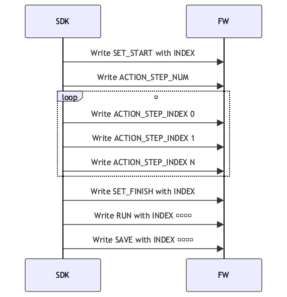
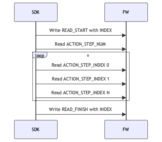
Action Sequence ACTION_CMD_ID/1098
Includes commands and action sequence Index. Action sequence
uint8_t cmd = 1;
uint8_t id = 2;
uint16_tregister_value = ((uint16_t)cmd << 8) + id;| CMD | Description |
|---|---|
| 1 | SET_START |
| 2 | SET_FINISH |
| 3 | READ_START |
| 4 | READ_FINISH |
| 5 | SAVE |
| 6 | RUN |
| Action ID | Description | |
|---|---|---|
| 1 | Built-in open action | W/R |
| 2 | Built-in fist action | W/R |
| 3 | Built-in two-finger pinch gesture | W/R |
| 4 | Built-in three-finger pinch gesture | W/R |
| 5 | Built-in side pinch gesture | W/R |
| 6 | Built-in single-finger tap gesture | W/R |
| 7 | Gesture sequence 1 | W/R |
| 8 | Gesture sequence 2 | W/R |
| 9 | Gesture sequence 3 | W/R |
| 10 | Gesture sequence 4 | W/R |
| 11 | Gesture sequence 5 | W/R |
| 12 | Gesture sequence 6 | W/R |
| ...... | ...... | W/R |
| 30 | Gesture sequence 24 | W/R |
Action Step Count Register/1099
Readable and writable, indicates the number of steps included in the action. Maximum of 8.
Action Step Parameter Register/1100Readable and writable, this represents the sequence, time, position, speed, and force parameters in the action step, where position refers to the finger position (°). When the position is set to -1, it indicates that the finger maintains its original angle, and the speed refers to the finger rotation speed (°/s).
| Register Address | Register Name | Description | |
|---|---|---|---|
| 1100 | index | Indicates the action sequence, range 0-8 | W/R |
| 1101 | duration_ms | Runtime | W/R |
| 1102 | ctrl type | Position time control: 1 Position speed control: 2 Current control: 3 Speed control: 4 | W/R |
| 1103 | positions[0] | Thumb Flex position value | W/R |
| 1104 | positions[1] | Thumb Aux position value | W/R |
| 1105 | positions[2] | Index position value | W/R |
| 1106 | positions[3] | Middle finger position value | W/R |
| 1107 | positions[4] | Ring finger position value | W/R |
| 1108 | positions[5] | Little finger position value | W/R |
| 1109 | expect_interval[0] | Thumb Flex Position Control Movement Time | W/R |
| 1110 | expect_interval[1] | Thumb Aux Position Control Movement Time | W/R |
| 1111 | expect_interval[2] | Index Finger Position Control Movement Time | W/R |
| 1112 | expect_interval[3] | Middle Finger Position Control Movement Time | W/R |
| 1113 | expect_interval[4] | Ring Finger Position Control Movement Time | W/R |
| 1114 | expect_interval[5] | Little Finger Position Control Movement Time | W/R |
| 1115 | speed[0] | W/R | |
| 1116 | speed[1] | W/R | |
| 1117 | speed[2] | W/R | |
| 1118 | speed[3] | W/R | |
| 1119 | speed[4] | W/R | |
| 1120 | speed[5] | W/R | |
| 1121 | force[0] | ||
| 1122 | force[1] | ||
| 1123 | force[2] | ||
| 1124 | force[3] | ||
| 1125 | force[4] | ||
| 1126 | force[5] |
Write the action sequence
Read action sequence
Actual Position Value / 2000
In order to achieve a control precision of 0.1°, the position values in physical quantity mode are uniformly amplified by 10 times before reporting (i.e., 1 represents 0.1°)
| Register Address | Finger | Register Value |
|---|---|---|
| 2000 | Thumb Flex | 0 - 1000 or Actual Angle (°) |
| 2001 | Thumb Aux | 0 - 1000 or Actual Angle (°) |
| 2002 | Index Finger | 0 - 1000 or Actual Angle (°) |
| 2003 | Middle Finger | 0 - 1000 or Actual Angle (°) |
| 2004 | Ring Finger | 0 - 1000 or Actual Angle (°) |
| 2005 | Little Finger | 0 - 1000 or Actual Angle (°) |
Actual Speed Values/2006
The speed value indicates the magnitude of speed, and the symbol indicates the direction of the motor finger movement.
| Register Address | Finger | Register Value |
|---|---|---|
| 2006 | Thumb Flex | -1000-1000 or Actual Speed (°/s) |
| 2007 | Thumb Aux | -1000-1000 or Actual Speed (°/s) |
| 2008 | Index Finger | -1000-1000 or Actual Speed (°/s) |
| 2009 | Middle Finger | -1000-1000 or Actual Speed (°/s) |
| 2010 | Ring Finger | -1000-1000 or Actual Speed (°/s) |
| 2011 | Little Finger | -1000-1000 or Actual Speed (°/s) |
Actual Current Value/2012
The current value indicates the magnitude of the current, and the symbol indicates the direction of finger movement for the motor.
| Register Address | Finger | Register Value |
|---|---|---|
| 2012 | Thumb Flex | -1000-1000 or Actual current value (mA) |
| 2013 | Thumb Aux | -1000-1000 or Actual current value (mA) |
| 2014 | Index Finger | -1000-1000 or Actual current value (mA) |
| 2015 | Middle Finger | -1000-1000 or Actual current value (mA) |
| 2016 | Ring Finger | -1000-1000 or Actual current value (mA) |
| 2017 | Little Finger | -1000-1000 or Actual current value (mA) |
Motor Status/2018
| Register Address | Finger | Register Value |
|---|---|---|
| 2018 | Thumb Flex | 0 - 3 |
| 2019 | Thumb Aux | 0 - 3 |
| 2020 | Index Finger | 0 - 3 |
| 2021 | Middle Finger | 0 - 3 |
| 2022 | Ring Finger | 0 - 3 |
| 2023 | Little Finger | 0 - 3 |
| Register Value | Description |
|---|---|
| 0 | Motor Idle |
| 1 | Motor Running |
| 2 | Motor Stalled |
| 3 | Turbo |
Key Status/2025
Read the key status. 0 means not pressed, 1 means pressed.
FW Version/3000
Read firmware version, 10 registers, maximum length of 20 strings.
The string is converted to multiple uint16_t registers in big-endian format.
| Big-endian uint16_t | Char | String |
|---|---|---|
| 0x302E, 0x302E, 0x342E, 0x5300 | 30 2E 30 2E 34 2E 53 00 | 0.0.4.S |
SN/3010
Read SN version, 10 registers, maximum length of 20 characters.
The string is converted to multiple uint16_t registers in big-endian format.
| Big-endian uint16_t | Char | String |
|---|---|---|
| 0x534E, 0x3132, 0x3334, 0x3738, 0x3930, 0x3132, 0x3334, 0x3500 | 53 4E 31 32 33 34 35 36 37 38 39 30 31 32 33 34 35 00 | SN123456789012345 |
Tactile Register Description - Capacitive
The fingertips of the capacitive tactile hand have tactile sensors. Due to structural differences in each finger, the arrangement of the fingers varies slightly; however, the data from each finger is collected through 6 channels, outputting a set of three-dimensional force and proximity force.
Configuration Register (Address Range: 4000–4014)
| Address Range | Function Description | Data Width | Read/Write | Description |
|---|---|---|---|---|
| 4000 Thumb 4001 Index Finger 4002 Middle Finger 4003 Ring Finger 4004 Little Finger | Haptic Switch Configuration | 2Bytes | R/W | 0: Off; 1: On |
| 4005 Thumb 4006 Index Finger 4007 Middle Finger 4008 Ring Finger 4009 Little Finger | Haptic Channel Reset Command | 2Bytes | W | Write 1 to trigger reset |
| 4010 Thumb 4011 Index Finger 4012 Middle Finger 4013 Ring Finger 4014 Little Finger | Parameter Calibration Trigger | 2Bytes | W | Write 1 to trigger finger parameter calibration |
Tactile Switch:The tactile switch supports the independent activation/deactivation of the tactile function of each finger. It supports read operations, where writing
1indicates that the tactile of the corresponding finger is activated, and0indicates that the tactile of the corresponding finger is deactivated. Reading1means that the tactile channel is in the activated state, while0means that the tactile channel is in the deactivated state.Channel Reset:The
Channel Resetregister accepts an input value of1to trigger the sensor collection channel reset command. During the execution of this command, the finger sensor should not be subjected to force.Parameter CalibrationThe
Parameter Calibrationregister accepts an input value of1to trigger the parameter calibration command. When the three-dimensional force values in the idle state are not0, calibration can be performed through this register. The execution time of this command is relatively long, and data during this period cannot be used as a reference. It is recommended to ignore the data within ten seconds after setting theParameter Calibrationregister.The finger sensor must not be subjected to force during the execution of this command, otherwise, the calibrated sensor data will be abnormal.
Tactile Firmware Version Information (Address Range: 4100–4140)
| Address | Corresponding Finger | Data Width | Read/Write | Description |
|---|---|---|---|---|
| 4100 | Thumb | 20 Bytes (10 uint16) | R | Firmware compilation date string |
| 4110 | Index Finger | 20 Bytes (10 uint16) | R | Firmware compilation date string |
| 4120 | Middle Finger | 20 Bytes (10 uint16) | R | Firmware compilation date string |
| 4130 | Ring Finger | 20 Bytes (10 uint16) | R | Firmware compilation date string |
| 4140 | Little Finger | 20 Bytes (10 uint16) | R | Firmware compilation date string |
- Haptic firmware version informationThe
versionregister is used to obtain the version of the haptic sensor, with a length of 10 registers. The string is converted to multiple uint16_t registers in big-endian format.
Five-finger three-dimensional force / proximity / tactile state (address range: 4200–4229)
| Address Range | Data Type | Size per Pointer | Total Size | Order | Description |
|---|---|---|---|---|---|
| 4200–4214 | 3D force data | 6 Bytes | 30 Bytes | Thumb → Pinky | 法向力2B + 切向力2B + 方向角2B |
| 4215–4224 | Proximity value | 4 Bytes | 20 Bytes | Thumb → Pinky | |
| 4225–4229 | Tactile state | 2 Bytes | 10 Bytes | Thumb → Pinky |
- Normal and tangential forces are 16-bit unsigned data. The unit of measurement is 0.01 N, so a value of 1000 represents 10 N (1000 * 0.01 N). The measurement range is from 0 to 25 N.
- The direction of the tangential force is 16-bit unsigned data. The unit is in degrees, with a numeric range of 0 to 359 degrees. The direction close to the fingertip is 0 degrees, rotating clockwise to a maximum of 359 degrees. When the value is 65535 (0xFFFF), it indicates that the tangential force direction is invalid.
- Proximity value is 32-bit unsigned data.
- The tactile state register is 16 bits, with high and low bytes representing different states:
The upper 8 bits: Used to indicate the packet sequence number for internal data updates of the sensor. If the value of this byte increases or changes, it indicates that the sensor output data has been updated.The lower 8 bits: Used to indicate the current status of the sensor, the bits are defined as follows:- Bit0 indicates that the original value is incorrect,
- Bit1 indicates that the original value has not been updated for a long time,
- Bit2 indicates a trigger timeout.
Due to the limitations of the Modbus-RTU protocol, to obtain complete 32-bit data, it is necessary to read two registers.
Single-point data reading (address range: 4250–4278)
| Address | Function Type | Data Format | Data Width |
|---|---|---|---|
| 4250 | Thumb three-dimensional force Proximity value Tactile state | Normal force(2B) + Tangential force(2B) + Direction angle(2B)+ Proximity value(4B)+ Status value(2B) | 6uint16 |
| 4256 | Index three-dimensional force Proximity value Tactile state | Normal force(2B) + Tangential force(2B) + Direction angle(2B)+ Proximity value(4B)+ Status value(2B) | 6uint16 |
| 4262 | Middle three-dimensional force Proximity value Tactile state | Normal force(2B) + Tangential force(2B) + Direction angle(2B)+ Proximity value(4B)+ Status value(2B) | 6uint16 |
| 4268 | Ring three-dimensional force Proximity value Tactile state | Normal force(2B) + Tangential force(2B) + Direction angle(2B)+ Proximity value(4B)+ Status value(2B) | 6uint16 |
| 4274 | Pinky three-dimensional force Proximity value Tactile state | Normal force(2B) + Tangential force(2B) + Direction angle(2B)+ Proximity value(4B)+ Status value(2B) | 6uint16 |
Raw Touch Channel Value Reading for Five Fingers (Address Range: 4300–4359)
| Address | Corresponding Finger | Channel Count | Bytes per Channel | Total Bytes | Description |
|---|---|---|---|---|---|
| 4300–4311 | Thumb | 6 | 4 Bytes | 24 Bytes | 4 bytes raw value per channel |
| 4312–4323 | Index Finger | 6 | 4 Bytes | 24 Bytes | 4 bytes raw value per channel |
| 4324–4335 | Middle Finger | 6 | 4 Bytes | 24 Bytes | 4 bytes raw value per channel |
| 4336–4347 | Ring Finger | 6 | 4 Bytes | 24 Bytes | 4 bytes raw value per channel |
| 4348–4359 | Little Finger | 6 | 4 Bytes | 24 Bytes | 4 bytes raw value per channel |
The tactile channel value is a 32-bit unsigned data.
Tactile Register Description - Piezoresistive
Piezoresistive sensors have 9 sampling points on each finger, distributed from the fingertip to the base of the finger, allowing for a comprehensive perception of tactile feedback on the fingertip surface.
Data Size per Sampling Point: 2 bytes (16 bits)Data Type:
Raw Value: ADC sampled value, suitable for debugging and internal calibration;
Calibrated Value: Pressure value converted to physical quantity, measured in g (grams).The choice of
Data Typecan be set via the holding register (0: Raw Value; 1: g value (default)).Supported Fingers: Thumb, Index Finger, Middle Finger, Ring Finger, Little FingerTo facilitate the quick acquisition of the overall force applied to the fingers, the following input registers are added for reading the combined force of the 5 fingers (Raw Value/Calibrated Value):
| Register Address | Finger | Description |
|---|---|---|
| 6001 | Thumb | 9-point force |
| 6002 | Index Finger | 9-point force |
| 6003 | Middle Finger | 9-point force |
| 6004 | Ring Finger | 9-point force |
| 6005 | Pinky Finger | 9-point force |
Users can read the 9-point pressure values for each finger through the registers and obtain the firmware version string information (10 bytes). Combined with the tactile data switch register control, the module can be started or stopped, saving resources.